
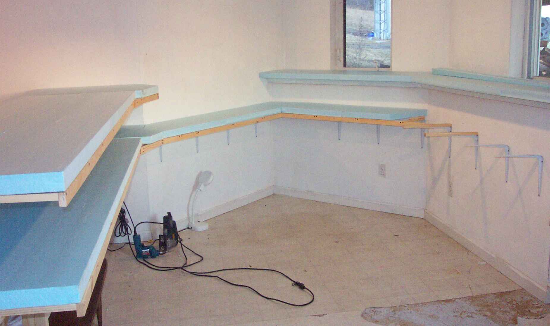
1 - The southeast corner of the layout room with some of the benchwork in progress
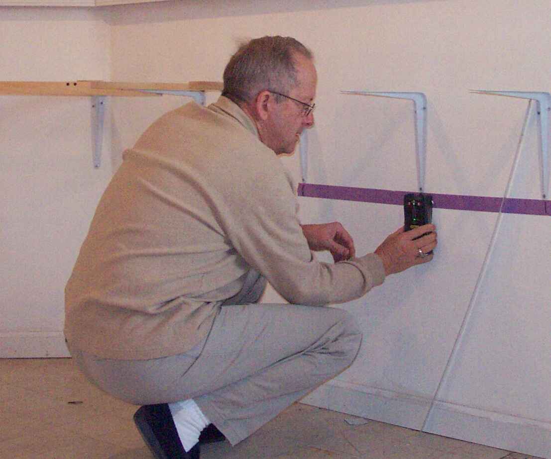
2 - A "stud finder" ensures brackets will be screwed to studs (picture taken later, but it shows the process)

3 - Painter's masking tape on the walls marks the height for the metal L brackets, and the stud finder used to mark the stud locations

4 - Brackets on the studs, joists on the brackets, and the edge stringers on the end of the joists. Note shims where the bracket wasn't quite a right angle!
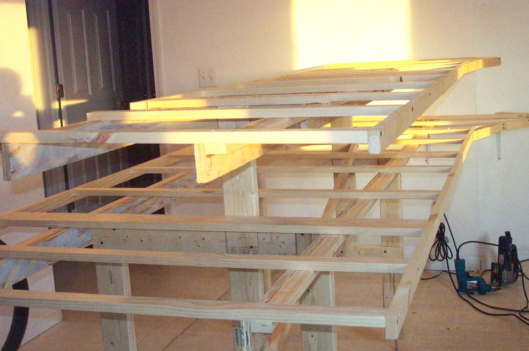
5 - Peninsula construction
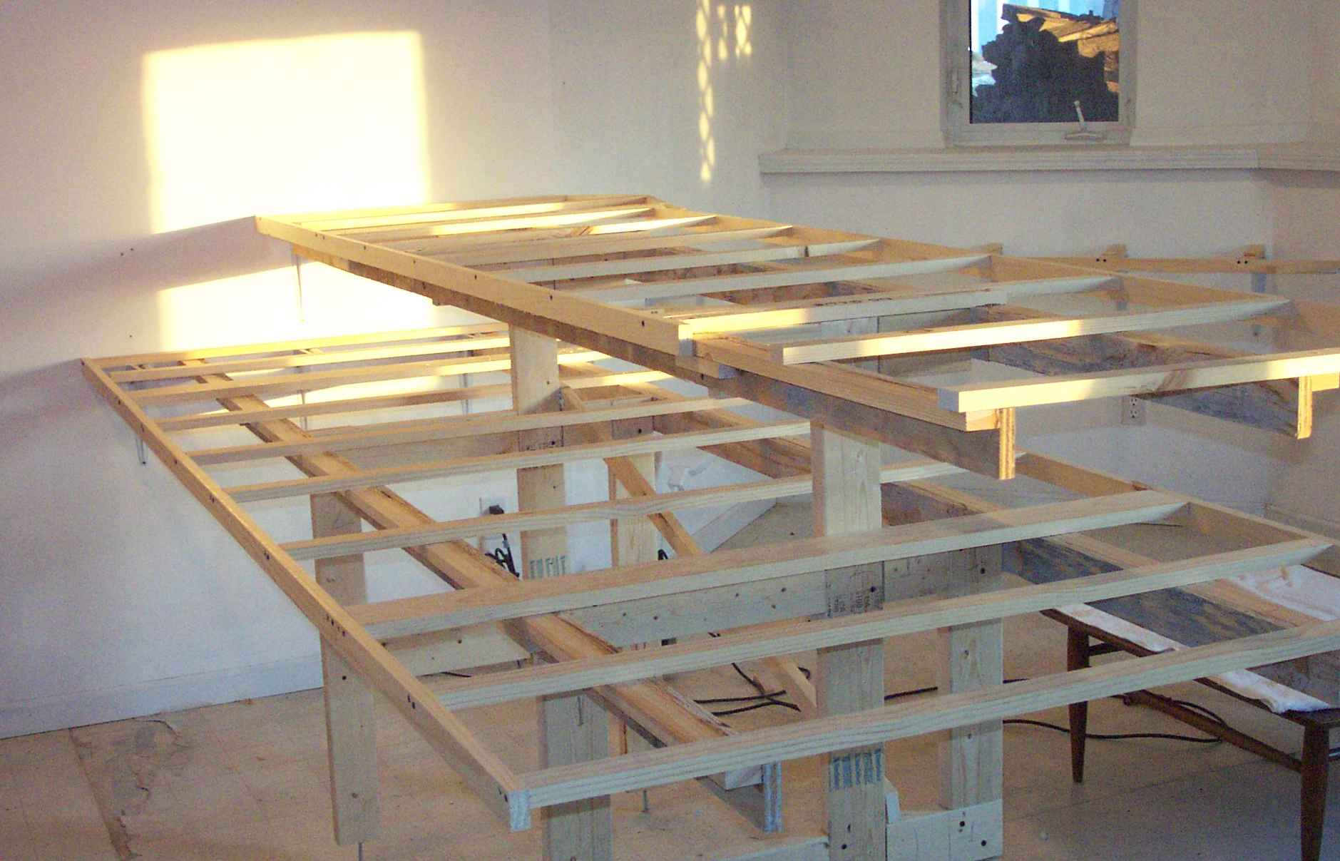
6 - Peninsula construction

7 - Peninsula construction

8 - 1 x 4 joists used where styrofoam sheets join
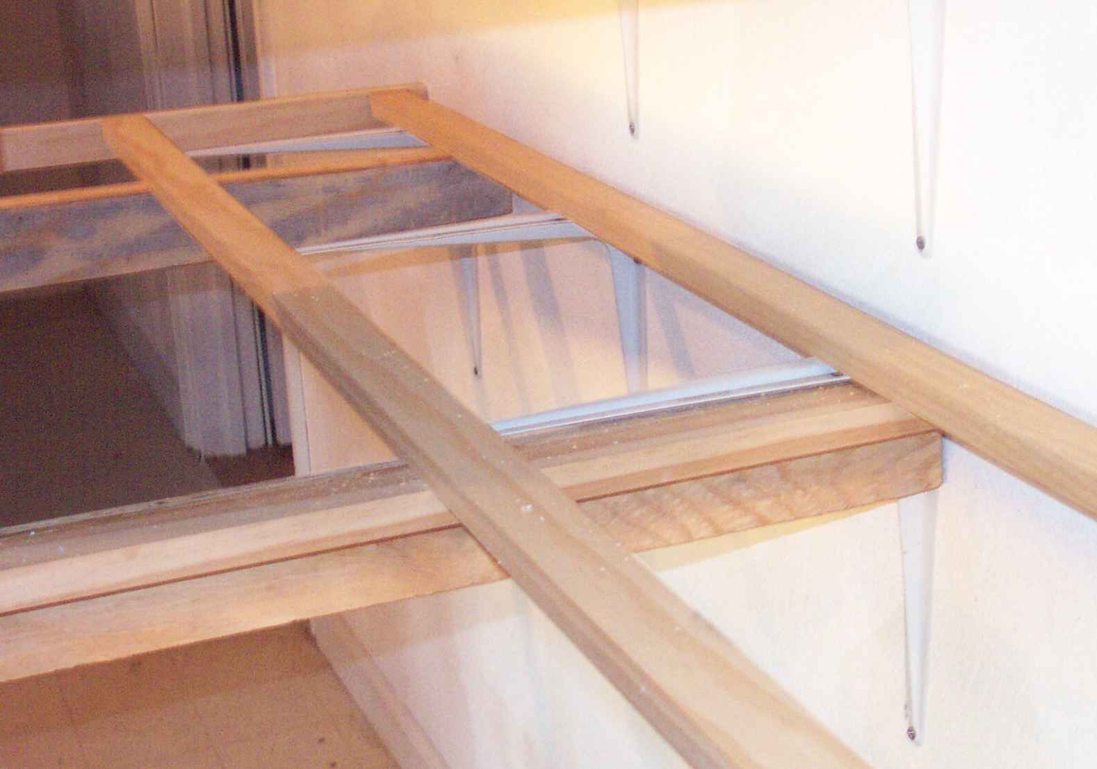
9 - Construction attaching peninsula to wall brackets - it will unscrew if needed for transport someday
10 - Fitting and gluing foam to joists

11 - Fitting and gluing foam to joists
Model Railroad Benchwork
Benchwork Construction
The Birchardville Railroad benchwork is both L-girder and joist construction for the peninsulas and around-the-walls construction with joists on commercial 10 x 12 inch metal L brackets screwed to the wall studs on the east and south walls.
These brackets also secure the wall ends of the peninsulas in place.
The peninsulas have a leg structure with 3/8 inch diameter lag bolts in their lower end to allow for height adjustment, even though the basement floor is quite level, they allowed me to adjust for miss-calculations between the height of the peninsula sections and the L brackets on the walls.
I made the L girders for the peninsulas from (nominal) 1 x 2 inch dimensional lumber edge glued to 3 inch wide strips cut from 3/4" plywood left over from a concrete forming job. Since the larger peninsula is 10 feet long, I spliced the girder sections during their fabrication so that the joints in the two girder pieces were two feet from the opposite ends of the girders.
I thought I'd left enough room between the upper and lower levels of the layout, but found after I'd built the supports that with the 2 inch thick extruded styrofoam material, that I wanted more space between the decks. As a result, I set the joists (more 1 x 2 material) on their wide side. They're close together and not too long both between the L-girders and at the outside cantilever ends, so I don't expect bending under load.
The extruded styrofoam material is glued with a construction adhesive designed for gluing styrofoam. When glued to the joists the whole thing is quite rigid.