Basement Layout Room

Overall Layout in Room
Lower Level Engine Facility

Upper Level Passenger Station
Our layout plans
Constraints GONE!
Well, the kids and grandkids are now in their own home. We can start building, right? Get out the tape measure and square and measure the part of the basement we've got agreement to use.
John Armstrong's Spokane and Puget Sound plan was an "N" shaped walk-in and around plan, with each leg of the "N" being two-sided. After adjusting his HO design to an N one, I found the big problem was not the tabletop itself but rather the spaces between the sections of the top. The tabletop sections could shrink by something like the difference between HO and N scale (87/160) and it would fit easily. I couldn't figure how to shrink the railroad operators by anything like the same ratio, so I wanted to make the spaces between the tabletop sections wide enough for operators to work and pass each other.
I ended up shrinking John's HO plan track ideas by a ratio of between 2/3 and 4/5 -- more or less 3/4 of the original size, but as I mentioned above, to make the operator spaces larger, I opened them up.
I do a lot of computer work, and found I didn't want to do the layout design without computer assistance. Asking on N-Scale.net and the Yahoo N-scale group led me to XTrkCAD, which, after a few "learning curve" issues, has proved to be a good tool. Denizens of the Yahoo XTrkCAD group were helpful in resolving the issues.
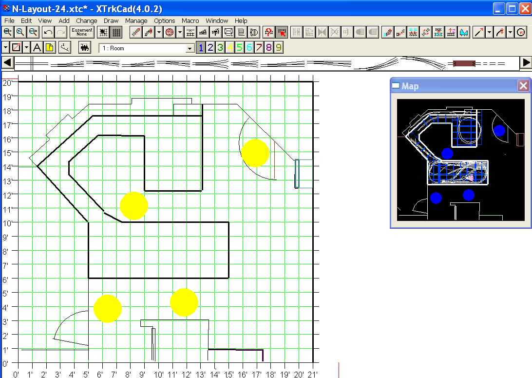
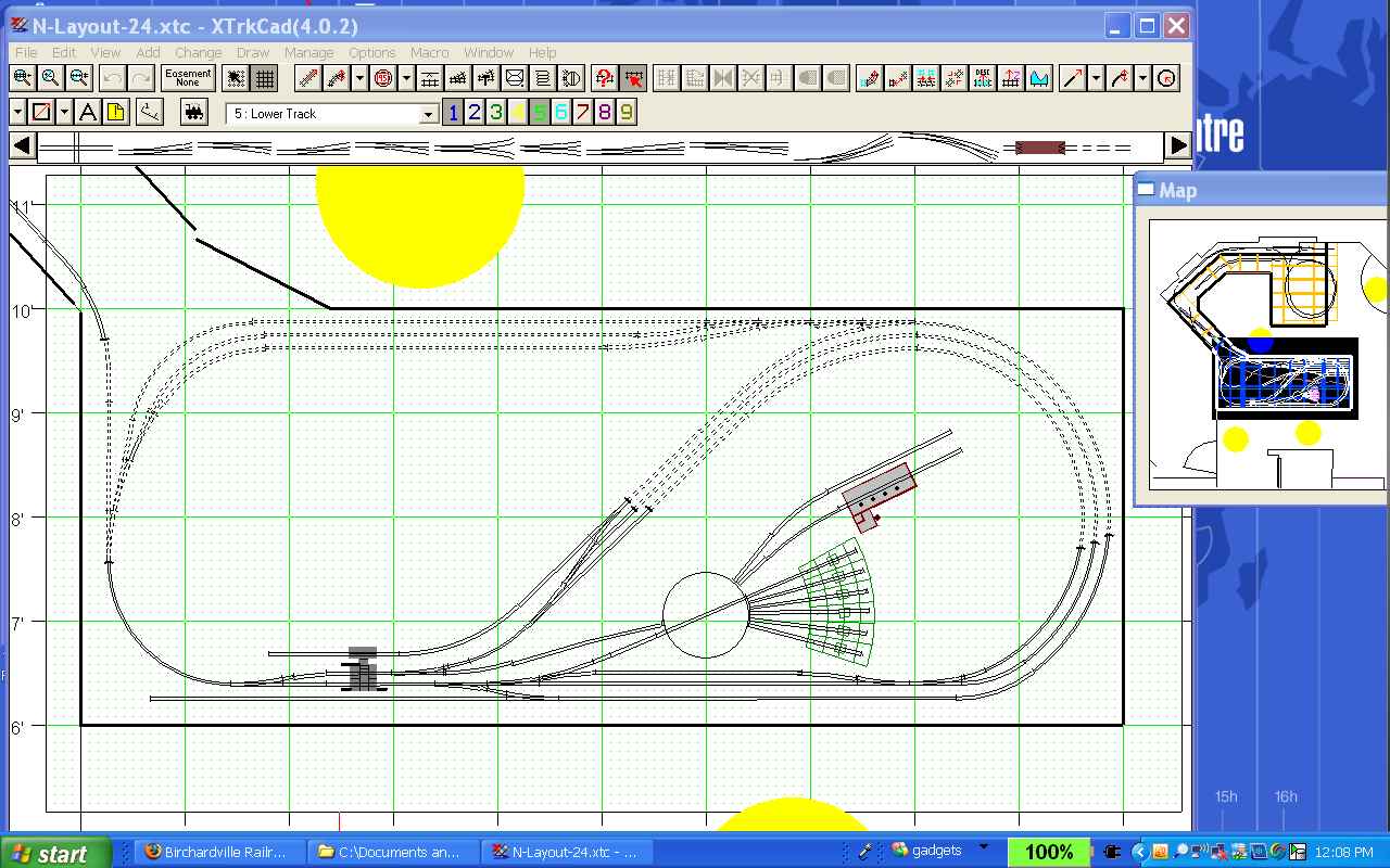
In the XTrkCAD screen shots on the left, the large yellow circles represent something like the size of operators, to show the scale of the spaces.
Clearly, the original John Armstrong design was warped and stretched and twisted and turned to fit into the odd-shaped basement space.
Looking at the first screenshot, the space just to the left of the layout is a separate basement room which has been designated as a scrapbooking sanctuary. There are two windows in this part of the basement wall (the south side of our house). This wall is represented to the top of the screen shots. From the left, the wall goes diagonally up and right with a window in the middle of that section, then horizontally to the right with another window, and finally diagonally down and right with a door to the outside (back yard).
I placed John's "Spokane" engine facility and yard on the lower level, and the "BC Junction" depot area on the upper level of the larger penninsula at the bottom of the upper screen shot. These two elements (engine facility and passenger station) are pretty much lifted from John's design with a little finagling because I have more scale space available.
The mainline runs from the lower left engine yard throat area up the east wall climbing along the south wall to the smaller penninsula where it spirals back left along the upper deck, across a model representing the famous Tunkhannock Creek Viaduct (built about 100 years ago by the Lackawanna and Western Railroad -- the prototype is about 30 miles from our home) to the upper deck passenger depot area.
Continue: